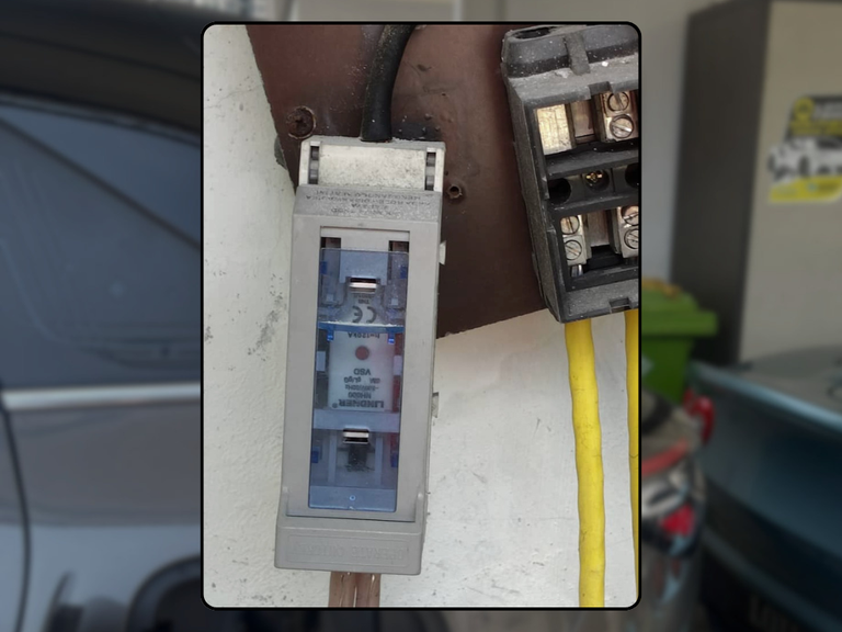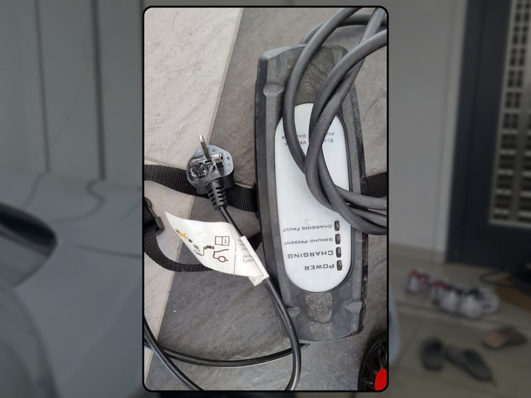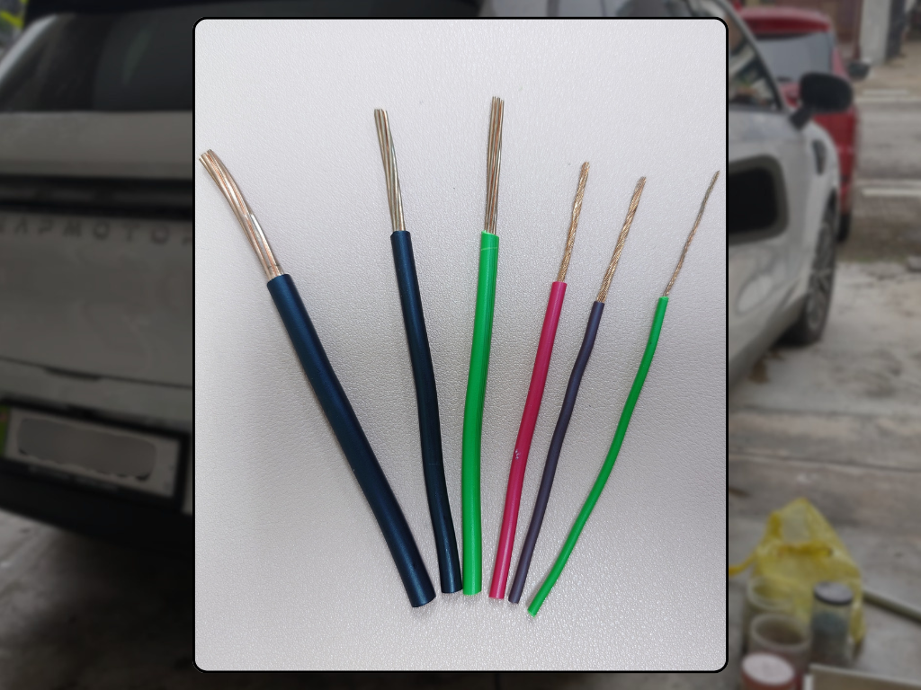
The same charger rating can require different cable decisions at different properties. EV charger cable sizing is not a universal number. Current, phase, route length, installation method, grouping, ambient conditions, voltage drop, fault performance and upstream protection all influence the design. For homeowners, specifiers and project teams, the practical objective is not to chase a perfect-looking component. It is to connect the equipment, fixed electrical installation, protection, operating behaviour and records into one traceable system.
That systems view matters because EV charging can run for hours and because later decisions are often made by someone who did not design the original installation. A homeowner, facility manager or maintainer needs evidence that answers three questions: what was intended, what is installed now, and what has changed. Where those answers are incomplete, the correct next step is targeted verification—not a confident guess.
Why the whole system matters
Technical decisions are safest when every claim is tied to the exact equipment and installation. The same power rating can be delivered by different architectures, and a familiar product name can cover several hardware variants. Designers and buyers should use current Malaysian guidance, the exact manufacturer manual and project-specific calculations together. Generic internet rules are useful prompts, not a design.
Confirm electrical duty
Charger rating, phase, current limit and expected continuous operating period define the design load. Begin with the evidence that can be confirmed today. This is important because an isolated observation can look reassuring while leaving the system boundary unclear. State the assumption, identify the component or record that can confirm it, and note the condition under which the conclusion remains valid.
Practical verification: Use the exact EVSE datasheet and intended configuration, not only the vehicle’s advertised charging power. A configurable charger must be assessed at its controlled maximum. Record the date, asset or circuit identity, responsible person and any limitation. If the evidence conflicts with the installed condition, treat that as an open item for competent review rather than selecting the more convenient answer.
Measure the real route
Length, bends, vertical runs, concealment, outdoor sections and crossings affect both electrical and physical design. Next, connect the design statement to what is physically installed. This is important because an isolated observation can look reassuring while leaving the system boundary unclear. State the assumption, identify the component or record that can confirm it, and note the condition under which the conclusion remains valid.
Practical verification: Trace the proposed path and identify containment, fire-stopping and reinstatement needs. Straight-line distance is rarely the installed cable length. Record the date, asset or circuit identity, responsible person and any limitation. If the evidence conflicts with the installed condition, treat that as an open item for competent review rather than selecting the more convenient answer.
Apply installation conditions
Ambient temperature, grouping, enclosure, thermal insulation and conductor material affect current-carrying capacity. Then test the operating assumption instead of accepting a status light. This is important because an isolated observation can look reassuring while leaving the system boundary unclear. State the assumption, identify the component or record that can confirm it, and note the condition under which the conclusion remains valid.
Practical verification: Record the installation method and derating conditions for calculation. A cable size copied from another house may not be suitable here. Record the date, asset or circuit identity, responsible person and any limitation. If the evidence conflicts with the installed condition, treat that as an open item for competent review rather than selecting the more convenient answer.
Coordinate voltage drops and protection
Conductor choice must work with voltage-drop limits, disconnection, fault level, protective devices and earthing. Finally, preserve enough information for the next decision-maker. This is important because an isolated observation can look reassuring while leaving the system boundary unclear. State the assumption, identify the component or record that can confirm it, and note the condition under which the conclusion remains valid.
Practical verification: Document calculations and the selected protective arrangement with the exact circuit. Larger cable alone does not fix an incorrect protection design. Record the date, asset or circuit identity, responsible person and any limitation. If the evidence conflicts with the installed condition, treat that as an open item for competent review rather than selecting the more convenient answer.
Build the evidence pack
Build a compact evidence pack around the decision. Keep the exact charger and protective-device identities, approved or as-built circuit information, inspection and test records, settings or configuration exports, fault and maintenance history, clear photographs and the names of responsible parties. For commercial sites, also keep the asset register, go-live acceptance, operating procedure and service records. For homes, keep the installer handover, user instructions and any insurer correspondence. Documents should be readable, dated and matched to the equipment; a folder of unrelated brochures is not an evidence trail.
Avoid the familiar shortcuts
Common mistakes are predictable: treating ‘it charges’ as proof of the fixed installation; choosing protection from a generic Type A/Type B slogan; increasing a setting after repeated trips; relying on remote status as a substitute for inspection; assuming single-phase supply is inherently unsafe; or treating dynamic load balancing as newly created capacity. Another mistake is turning a public incident into a product accusation before investigators publish a finding. These shortcuts reduce lead quality because they start with an answer instead of the property, equipment and evidence.
A practical decision path
Use a three-stage decision. First, collect the information described above without disturbing live equipment. Second, compare it with current ST guidance, the exact EVSE instructions and the real operating need behind ‘EV charger cable size; charger cable distance’. Third, commission only the inspection, testing, remediation or capacity study needed to close the identified gaps. This produces a scope that an owner can understand, and a technical team can price responsibly. It also avoids replacing compliant equipment simply because documentation was initially poor.
Important limitation
Cable selection is electrical design work. Do not use this article as a sizing table or alter an installation without project-specific calculations and suitable professional verification.
Conclusion
The goal is not to make charging sound frightening. It is to make the installation explainable. When the asset, circuit, protection, operating behaviour and records agree, owners can make better decisions and maintain the system with confidence. When they do not agree, the gap becomes a defined technical task rather than a vague fear.
Let our obsession with quality protect your safety.
Because when it comes to EV charging and electrical systems, there’s no room for compromise.
Need your EV charger or electrical setup professionally inspected?
📲 WhatsApp Us: https://wa.me/60125954786
Stay connected with us:
📷 Instagram: https://www.instagram.com/InnovativeGreenPowerMY
📘 Facebook: https://www.facebook.com/innovativegreenpower
🎥 YouTube: https://www.youtube.com/@IGPEVCharging-ir8rv
🖥 Website: https://www.innovativegreenpower.com