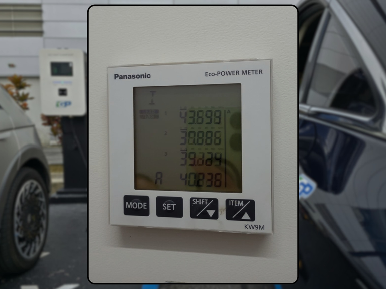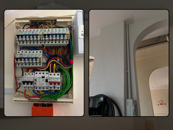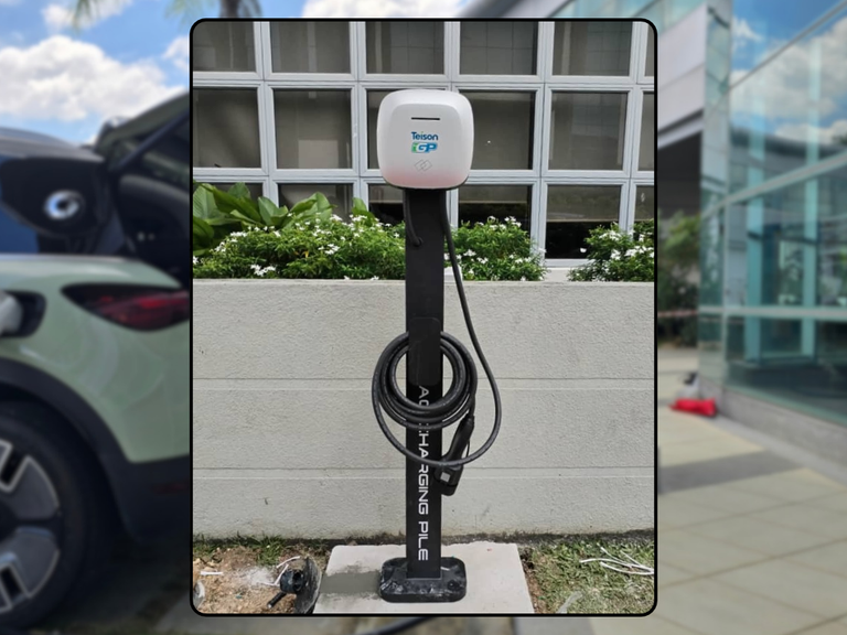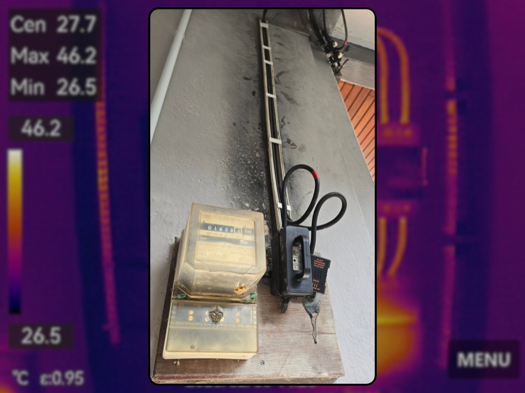
The cable route may look neat, but the highest-risk point can be a hidden termination. EV charging can hold a substantial load for hours. That makes small resistances at joints, terminals and damaged conductors important, especially on long routes or installations altered after handover. For homeowners with long routes or older DBs, the practical objective is not to chase a perfect-looking component. It is to connect the equipment, fixed electrical installation, protection, operating behaviour and records into one traceable system.
That systems view matters because EV charging can run for hours and because later decisions are often made by someone who did not design the original installation. A homeowner, facility manager or maintainer needs evidence that answers three questions: what was intended, what is installed now, and what has changed. Where those answers are incomplete, the correct next step is targeted verification—not a confident guess.
Why the whole system matters
For a home, the boundary starts at the available supply and distribution board, follows the dedicated charging circuit and protection, and ends only after the wallbox, cable, connector and vehicle interface. Household loads, route conditions and user habits sit around that chain. Owners can collect records and observe accessible condition, but opening switchboards, changing protective devices or testing live circuits is work for suitable electrical professionals.
Design the full route
Conductor size is only one input; route length, installation method, grouping, ambient temperature and voltage drop also matter. Begin with the evidence that can be confirmed today. This is important because an isolated observation can look reassuring while leaving the system boundary unclear. State the assumption, identify the component or record that can confirm it, and note the condition under which the conclusion remains valid.
Practical verification: Compare design assumptions with the actual path through roof spaces, trunking, buried sections and outdoor transitions. A neat visible section cannot validate concealed thermal conditions. Record the date, asset or circuit identity, responsible person and any limitation. If the evidence conflicts with the installed condition, treat that as an open item for competent review rather than selecting the more convenient answer.
Treat terminations as components
Poor torque, contamination, conductor damage or incompatible lugs can create local resistance and heat. Next, connect the design statement to what is physically installed. This is important because an isolated observation can look reassuring while leaving the system boundary unclear. State the assumption, identify the component or record that can confirm it, and note the condition under which the conclusion remains valid.
Practical verification: Have accessible terminations inspected and maintained using manufacturer instructions and appropriate safe procedures. The hottest point may be a connection rather than the middle of a correctly sized cable. Record the date, asset or circuit identity, responsible person and any limitation. If the evidence conflicts with the installed condition, treat that as an open item for competent review rather than selecting the more convenient answer.
Watch for field indicators
Discolouration, odour, softened plastic, buzzing, intermittent charging or repeated protective operation need investigation. Then test the operating assumption instead of accepting a status light. This is important because an isolated observation can look reassuring while leaving the system boundary unclear. State the assumption, identify the component or record that can confirm it, and note the condition under which the conclusion remains valid.
Practical verification: Stop normal use when significant symptoms appear and preserve photographs and fault history for the assessor. Symptoms are not a diagnosis, but they help prioritise inspection before damage escalates. Record the date, asset or circuit identity, responsible person and any limitation. If the evidence conflicts with the installed condition, treat that as an open item for competent review rather than selecting the more convenient answer.
Use testing proportionately
Electrical measurements and, where justified, thermography can support a risk-based assessment under representative load. Finally, preserve enough information for the next decision-maker. This is important because an isolated observation can look reassuring while leaving the system boundary unclear. State the assumption, identify the component or record that can confirm it, and note the condition under which the conclusion remains valid.
Practical verification: Define what is being tested and remember that a thermal image is a snapshot influenced by load and ambient conditions. Thermography is optional evidence, not a universal substitute for design review, torque control or electrical testing. Record the date, asset or circuit identity, responsible person and any limitation. If the evidence conflicts with the installed condition, treat that as an open item for competent review rather than selecting the more convenient answer.
Build the evidence pack
Build a compact evidence pack around the decision. Keep the exact charger and protective-device identities, approved or as-built circuit information, inspection and test records, settings or configuration exports, fault and maintenance history, clear photographs and the names of responsible parties. For commercial sites, also keep the asset register, go-live acceptance, operating procedure and service records. For homes, keep the installer handover, user instructions and any insurer correspondence. Documents should be readable, dated and matched to the equipment; a folder of unrelated brochures is not an evidence trail.
Avoid the familiar shortcuts
Common mistakes are predictable: treating ‘it charges’ as proof of the fixed installation; choosing protection from a generic Type A/Type B slogan; increasing a setting after repeated trips; relying on remote status as a substitute for inspection; assuming single-phase supply is inherently unsafe; or treating dynamic load balancing as newly created capacity. Another mistake is turning a public incident into a product accusation before investigators publish a finding. These shortcuts reduce lead quality because they start with an answer instead of the property, equipment and evidence.
A practical decision path
Use a three-stage decision. First, collect the information described above without disturbing live equipment. Second, compare it with current ST guidance, the exact EVSE instructions and the real operating need behind ‘Cable heat / loose connection / long run’. Third, commission only the inspection, testing, remediation or capacity study needed to close the identified gaps. This produces a scope that an owner can understand and a technical team can price responsibly. It also avoids replacing compliant equipment simply because documentation was initially poor.
Important limitation
Never tighten electrical terminals or open energised enclosures as a DIY check. Correct torque and safe isolation require the right equipment, instructions and competent person.
Conclusion
The goal is not to make charging sound frightening. It is to make the installation explainable. When the asset, circuit, protection, operating behaviour and records agree, owners can make better decisions and maintain the system with confidence. When they do not agree, the gap becomes a defined technical task rather than a vague fear.
Let our obsession with quality protect your safety.
Because when it comes to EV charging and electrical systems, there’s no room for compromise.
Need your EV charger or electrical setup professionally inspected?
📲 WhatsApp Us: https://wa.me/60125954786
Stay connected with us:
📷 Instagram: https://www.instagram.com/InnovativeGreenPowerMY
📘 Facebook: https://www.facebook.com/innovativegreenpower
🎥 YouTube: https://www.youtube.com/@IGPEVCharging-ir8rv
🖥 Website: https://www.innovativegreenpower.com